
Heat Treating Oven
I've wanted a heat treating oven for years for hardening/tempering machine parts and tooling. I've "borrowed" one when needed in the past. However, having one would be handy. In building a small internal combustion engine, a Webster, I found the need to heat treat piston rings. This was the last push to build an oven for my shop. So, in 2014 I built one. This build log tells the story.
WARNING: This information documents the oven I've built. If you use anything here to build a similar oven, I will not be liable for any use or misuse of this information. This project deals with hazardous voltages, temperatures and substances that you must understand. Work with them at your own risk. If you are not knowledgeable about electricity consult a qualified electrician.
Research
There are several (many) similar build logs on the Internet. Most shop built heat treating ovens are being used for making knives. Also, good information can be found searching through ceramic kiln sites. I learned several basic "rules" surfing these sites:
- Use "Insulating Fire Brick" (IFB) for construction and insulation. These are very soft and light with excellent heat and insulating properties. They typically come 9" x 4.5" x 2" and 9" x 4.5" x 3". These IFBs withstand temperatures up to 2300°F, which is adequate for nearly all heat treating processes.
- Cutting these bricks is quite easy. They can be cut with wood working equipment, saws, routers etc. However, they are very abrasive and will dull standard cutting tools quickly. Cutting is very dusty producing fine grit which is hard on power tools. For ones health, the dust should not be inhaled. I found the bricks to be quite fragile. They can be damaged by clamping for cutting or lightly dropping on a hard surface.
- Many people place the bricks without mortar. Others use mortar. If mortar is used it needs to be adequate for this high temperature application. The major reason for not using mortar, mainly for kilns, is the ability to take apart and move the oven.
- A 2" wall of IFB is marginal and 3" seems to be OK. This for a small oven some 6" to 12" square inside dimension.
- Electric heating elements are most common with manufacture from a more heat resistant metal than nichrome (1400°F) being required. Kenthal (2300°F) is commonly used. Heating the elements near their maximum temperature will shorten their life.
- Builders are using, in the USA, both 120VAC and 240VAC for power. The 120VAC seems marginal, at least with "standard" breakers.
- Control is typically done using a temperature controller connected to a thermocouple inside the oven. K Type thermocouples are common. Inexpensive temperature controllers, with quite sophisticated options, are available. The controller typically controls a Solid State Relay (SSR) which cycles current to the heaters. An SSR, instead of a relay, allows rapid current cycling so the heating elements maintain a more constant temperature. These temperature swings can shorten the life of the elements.
- A cut off switch is needed to turn off element power when the door is open. This is needed for safety.
DESIGN
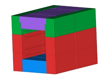
I spent some time arranging bricks in a CAD system. This to have 3" walls and minimal waste in cutting. Another criteria was to span the roof with one brick (9"). Finally, the length of the elements must meet specification. I purchased 2 element coils from Budget Casting Supply, Sonora, CA. They are for a 120V supply and my design uses two in series powered with a 240VAC single phase supply. These coils need to be stretched to at least 60", so another requirement. Both together give 3100 watts.
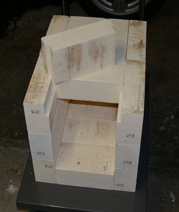
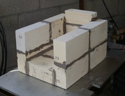
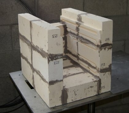
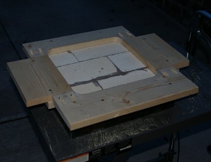
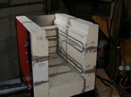
The final layout is shown in Figure 1 and 2. The roof bricks are undercut due to the depth limit of my table saw, I couldn't cut the side bricks a full 3" so cut them 1 1/2" and the roof bricks 1 1/2".
 |
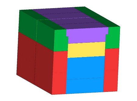 |
| Figure 1 : Left Side | Figure 2 : Back |
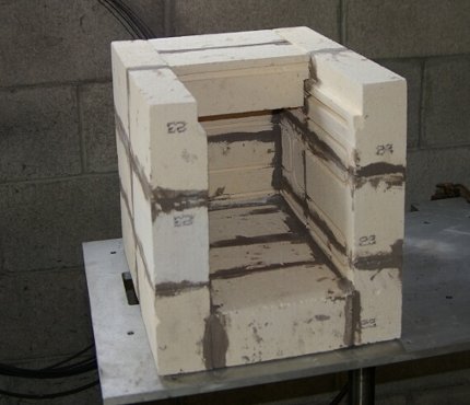
The door is made of 6 bricks oriented 3" thick. See Figure 3. The slot is for a length of ceramic rope for sealing. Note glass rope, such as for wood stoves, will melt here. The door seal is 1/2" rope.
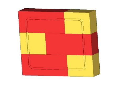 |
| Figure 3: Door |
This totals 22 IFB blocks for the oven and 6 for the door, a total of 28, each being 9"x4.5"x3". This meets the requirements giving outside measurement of 14" W x 18" D x 13.5" H. The internal dimensions are then 8" W x 15" D x 7.5" H. That's 0.52 ft³ volume and 4.1 ft² inside surface area.
With 3100 watts heating elements this gives 5960 watts/ft³ on volume and 763 watts/ft² on inside area. A review of small commercial heat treating ovens shows averages of 5400 watts/ft³ and 750 watts/ft² respectively. The design is well within the normal range of available ovens.
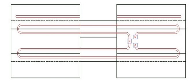
Figure 4 shows the arrangement of the slots for heating elements. The drawing is a fold out of the bricks seen from the inside of the oven. The dotted lines show where the floor and roof are. Slots for the heating elements are oriented to avoid, as much as possible, joints in the bricks. Leads pass through the oven wall on the side for power connection. Most ovens have these wires passing through the back wall. This would be fine, but for my particular location I have connections on the side work out better.
 |
| Figure 4: Element Slots |
There are additional slots above the roof line. For ease of installing and replacing heating elements the roof bricks are to be removable. These slots accommodate ceramic rope which should seal the roof bricks, but still allow removal. These slots for 3/8" rope.
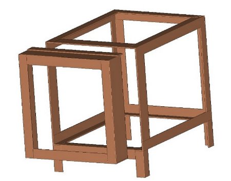
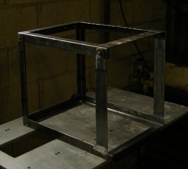
The frame is welded from 1 1/4" x 1/8" angle iron and 1/8" flat bar stock. The layout of the frame is shown in Figure 5. Inside the framework will be six sheet metal walls. They will be set in place and simply be trapped between the frame and bricks. The IFBs are fragile enough to need this protection.
 |
| Figure 5: Frame |
The main frame is primarily of 1 1/4" angle iron. The front side and top are 2" x 1/8" bar stock. This leaves bare bricks at the front of the oven to seal with the door. For simplicity, the main door frame was made of 3" x 1/8" bar with 1" x 1/8" on the front. This is likely overkill, but 1/8" stock is easy to obtain, weld and work with. I put one strip on the top of the door to overhang the main frame. This is to better seal this joint when closed.
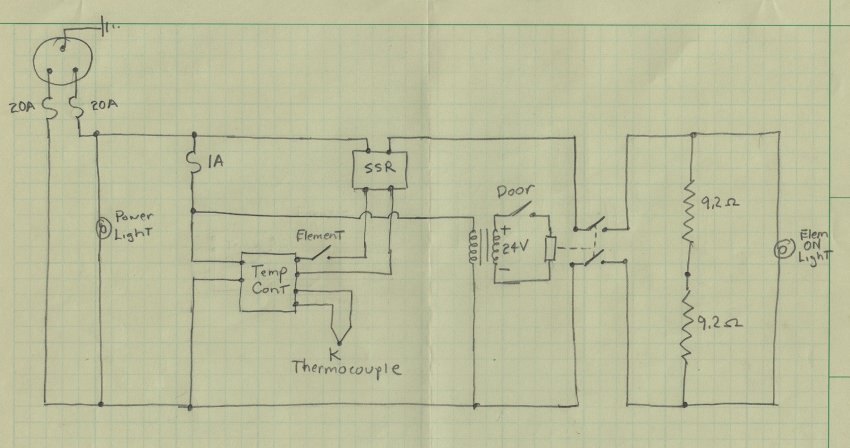
Figure 6 shows the control circuit diagram. I decided to use a single phase 240V AC circuit, the same plug used for my welder. The elements will draw 13A and I fused the circuit for 20A. Both legs of a 240V circuit are hot so one fuse on each leg. I didn't include an on/off switch planning to just use the wall plug. A green power light is illuminated when the unit is plugged in. The temperature control is provided by a unit from Omega Engineering. It is powered from the 240V circuit, reads a K type thermocouple, and drives a Solid State Relay (SSR). A switch is placed between the controller and the SSR. When the switch is open, the SSR is open, no power is applied to the heating elements.
 |
| Figure 6: Circuit Diagram |
A door switch is needed for safety. I also didn't want to run 240V out to this switch, so I included a 24V DC supply to run this door switch circuit. The juice from the 24V supply energizes a relay to allow power to the heating elements only when the door switch is closed. A two pole switch is needed since both legs of the 240V supply is at 120V relative to ground. The power for the 24V supply, and thus the relay, is taken before the SSR. If it were after the SSR the power, and thus relay, would cycle rapidly creating excessive wear on the relay contacts. A 1 amp fuse protects the temperature controller and 24V supply so smaller wiring can be used for these circuits.
That's enough for design. So on with the construction and more on the fly design.
CONSTRUCTION
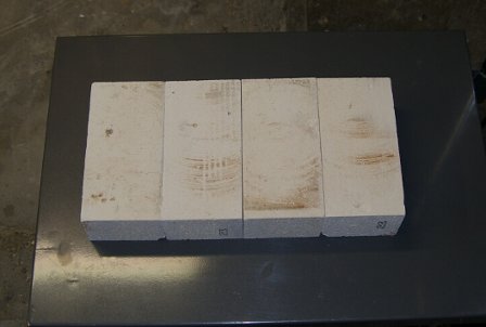
The first task was to cut the bricks to size. I have a very old table saw which I used for this. Another saw, even a hand saw, would work. But the precision of a table saw helps down the road when fitting the bricks together. I went to a local home supply to buy a cheap blade for this, and found an inexpensive tile/brick blade for $12. This is what I used and it worked very well. Figures 7 through 12 shows the cut bricks and their orientation.
 |
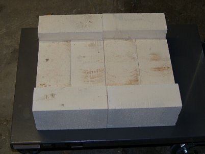 |
| Figure 7: Floor Bricks | Figure 8: Lower Side |
 |
 |
| Figure 9: Middle Side | Figure 10: Back |
 |
 |
| Figure 11: Top Side | Figure 12: Top |
I built a simple jig to route the element slots. An old router was used (with broken base plate) here to avoid harming a newer router. A simple tool for this routing was made. Actually three tools, slots for the heating elements, the ceramic rope slots for the roof bricks, and slot for the door ceramic rope. The tools are simply made the correct diameter, cut down on one end to fit the router 1/4" collet. The business end was simply milled flat one half was through. These were made from drill rod (silver steel) and heat treated, heated to cherry red and dunked in water. I didn't tempering these but used them full hard. Figure 13 shows the tool for cutting element slots. Figure 14 shows the router and routing jig.
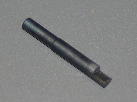 |
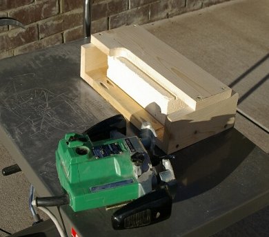 |
| Figure 13: Routing Tool | Figure 14: Routing Jig |
Once the main oven bricks were cut and routed it was time to mortal them together. "Super 32 Refractory Mortar" was obtained from High Temp Inc., an Ebay company. The IFB also came from them. I put a thin layer of mortar on both sides and then "slid" together. I also tried putting mortar on only one side and this also seemed to work. This mortar dries quickly leaving little time to adjust brick position. I put a little water on the bricks with a sponge before mortaring them. I read this somewhere and it helps delay set up a little. However, the mortar needs to set up for some time before moving them around. Before allowing this time I dislodged a few bricks trying to do too much at a time. I tried for the thinnest seeam I could obtain and waited overnight.
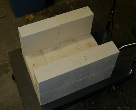
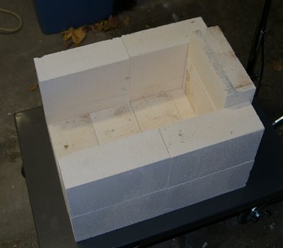
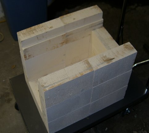
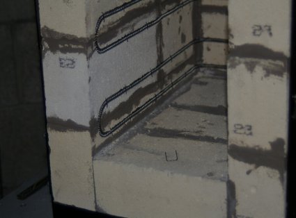
Figures 15 through 28 shows the progression of brick lay up. You can see the routed slots in these pictures. Be sure to clean the slots of mortar as they are put together. Once set up the mortar is much harder than the IFB. The slots for elements are evident in all the pictures. The last three show the slots for ceramic rope to seal the roof bricks. For the roof, I mortared the front two and the back two bricks together.
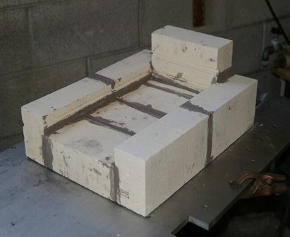 |
 |
| Figure 15: Mortared 1 | Figure 16: Mortared 2 |
 |
 |
| Figure 17: Mortared 3 | Figure 18: Mortared 4 |
After the bricks were mortared together and set, the frame was constructed. Figure 19 shows the basic structure without the legs. I built this around the bricks leaving an 1/8" or so slop. It would be possible, as called for in the design, to slide the brick oven in from the front. However, the bricks are fragile and it was decided to make the top of the frame removable. Tabs and screws hold the top frame in place as shown in Figure 19. Hot rolled steel was used and wire brushed to get the crud off.
The front face has no frame covering it. The design calls for the front of the main oven to seal with the door brick to brick, but for the ceramic rope seal. This seemed easier and better than trying to build a steel from around the front.
Figure 20 shows the left side of the frame after the legs were welded on. Each leg has a 1/4" thick base plate with hole for threaded leveling pads. Four studs were welded in to support a "tower" to hold the electrical box.
 |
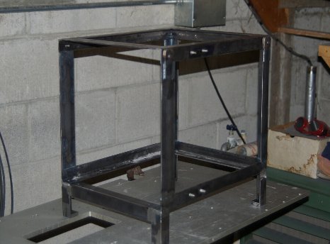 |
| Figure 19: Frame Front | Figure 20: Frame Left |
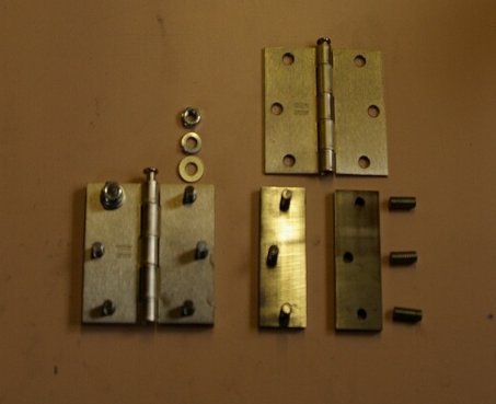
I used house door hinges as shown in Figure 21. 1/4" plates were drilled and threaded to match the hinge mounting holes. Studs were then welded into these plates and smoothed on the back side. The plates were then welded to the steel frame. Figure 22 shows the first try.
 |
 |
| Figure 21: Hinge | Figure 20: Hinges, First Try |
The door was made up of six bricks in a steel frame. Figure 23 shows the bricks in their frame. The frame was made of 3"x1/8" steel on the sides and 1"x1/8" steel on the front. As with the main frame, sheet metal protected the bricks at the front. This figure also shows a piece of dry wall to which course sandpaper was glued with contact cement. This was used to flatten the door bricks after they were mortared together. It worked but care was needed since the mortar is much harder than the bricks. The bricks at the front of the oven were also flattened with this sanding block.
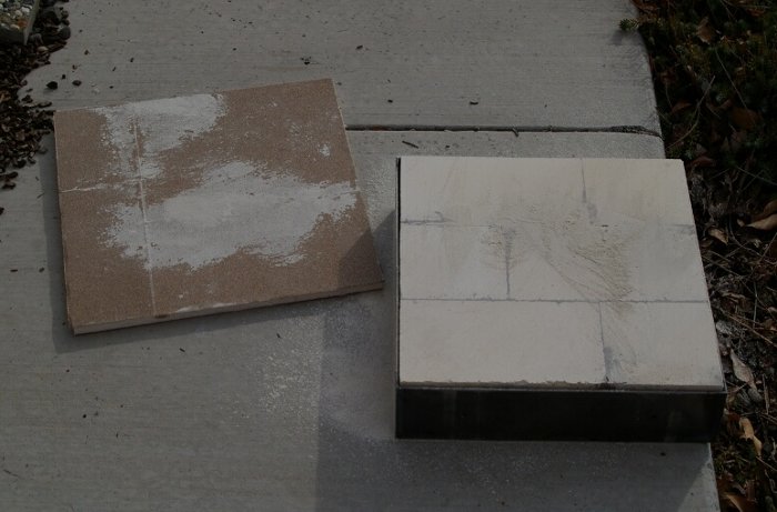 |
| Figure 23: Door Frame & Sanding Block |
The slot for the door seal was routed into the door in the same manner as the element slots above. Figure 24 shows the jig used for this. The bricks were mortared together before routing here which caused some problems. The mortar was hard to cut with my improvised tooling. It worked, but if done again I'd be tempted to cut the slots, then mortar. Pros and cons each way.
Figure 25 shows the door with slot cut and ceramic rope seal installed. I thought I'd need some glue to hold the door and roof seals in place. After putting the ceramic rope in place though, it fit well enough to not need gluing.
 |
 |
| Figure 24: Door Slot Jig | Figure 25: Door Seal |
Unfortunately the hinges were welded to the main frame too far back. This was discovered once the door was completed and placed in position. I decided to cut that left front post out of the frame and replace it. Thankfully this was less work than I anticipated.
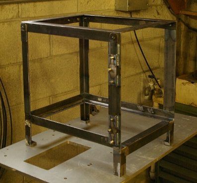
Then, the hinges and hinge plates were put in a more reasonable location starting with the door. Figure 26 shows the welding of the hinge plates to the door. A threaded rod was placed through both hinge pin holes to maintain alignment. The threaded rod turned out to be the right diameter. The hinge plates were tacked in place.
Figure 27 shows the next step, clamping the door in place and tacking the hinge plates to the main frame. Once tacked in place and checked, the bricks were removed, the hinges removed and the plates welded in place. Figure 27 shows the sheet metal sides placed in the frame. They stay in place well so were not welded or otherwise positively held.
 |
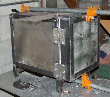 |
| Figure 26: Hinge Jig | Figure 27: Hinge Attachment |
That's nearly it for the main structure. A draw latch was put on the right side to hold the door closed. Also, threaded holes were made to hold a door switch along with an adjustable plunger welded in place to close the switch. Then the frame and sheet metal walls were cleaned up and painted. The outside of the oven likely doesn't get too hot, but to be on the safe side I used high temperature engine paint.
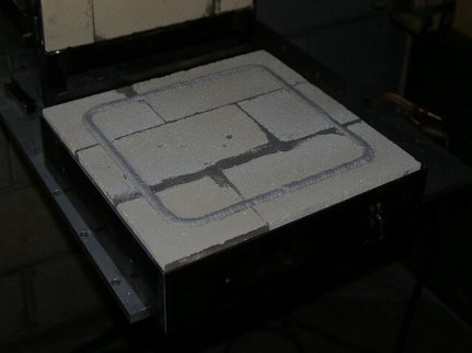
Once two coats of paint had dried well, the oven and door were put back together. Well, the top of the frame and roof bricks were left off for installation of the heating elements. Figure 28 shows the stretched elements in place. The elements needed to be stretched to 75". I clamped one end of the element in a vice, grabbed the other end with vice grips, and stretched. The first stretched evenly, no problem. However the second didn't, it expanded more in some places than others. I was able to compress the most egregious errors but this took some time with needle nose pliers. So, I would pay more attention next time and make sure the element stretched evenly from the start. I don't know if the uneven stretch will cause problems or not. Worst case would be replacing the element(s) which wouldn't be too hard.
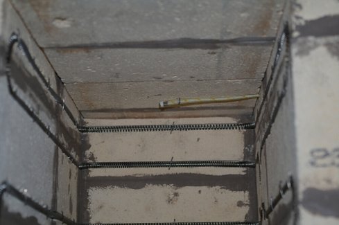
The elements need to be held in place with "kiln staples". These are high temperature wire bent in the shape of a staple. Figure 29 shows the staples installed and one laying on the floor. I've read these should be placed every 3" to 4". I used 44 staples all together. I purchased the staples cut and bent into horseshoes. I ended up re-bending them for a longer span between legs. As they came they wouldn't span the coils, and wouldn't fit easily between coils (to only hold the bottom of the elements). It may have been as easy to purchase "kiln staple wire" and cut/bend from that.
 |
 |
| Figure 28: Elements | Figure 29: Kiln Staples |
The thermocouple was brought in at the roof line above the element connections, Figure 30. It's in a flexible (cloth) sheath so easy to snake through the hole. The holes for the elements were drilled using thin welding rod cut flat at an angle at the tip. The thermocouple hole needed a 1/4" drill bit. Twisting by hand worked easily. These were drilled in the bricks then located on the sheet metal side. Figure 31 shows the wiring as it came through the side of the oven.
 |
 |
| Figure 30: Thermocouple | Figure 31: Connections |
I tapped several 1/4-20 holes in the steel frame before painting. There were six spaced around the door frame, see the white dots in Figure 31. The hinges covered two of these so I added on at the center of that side. After the door was installed and the hasp closed holes were drilled into the bricks through these tapped holes. Then 3/4" screws were installed to hold the door bricks in place. I placed similar tapped holes at the front of the main frame for the same purpose. Two holes underneath to hold the main oven in place and two on top to hold the roof bricks. Holes were made in the sheet metal top and bottom pieces. I've since found the main oven and bricks stay put well so I've not installed these screws. But nice to have if things start to shift later. I also put tapped holes in the frame at the back of the oven. These were for pushing the main oven and roof bricks forward by pushing on the sheet metal back wall with set screws. These also haven't been needed.
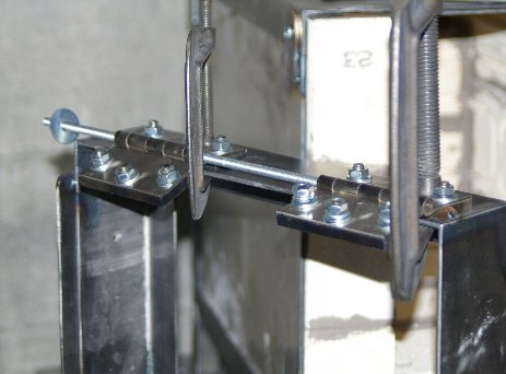
Figure 32 shows the hinge side at this point. Figure 33 shows the draw latch and door switch set-up mentioned earlier. The leveling feet can be seen in these figures.
 |
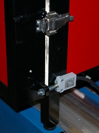 |
| Figure 32: In Process Hinge Side | Figure 33: Latch & Switch |
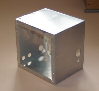
So, you'd think (as I did) that it's nearly finished. However, the electrical box and wiring took some time. I looked for an electrical box locally but could not find one. The closest was 6"x6"x4" but this was just slightly too small. I looked around the Internet but couldn't tell what would work best just from pictures. So I decided to build the control box.
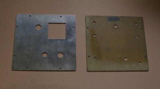
If you're reading this I'm confident you've built boxes before, but here are the basics and some of the specifics I ran into. Figure 34 shows the perimeter of the box, simply two pieces bent and riveted together. Figure 35 shows the front and back pieces.
 |
 |
| Figure 34: Box Perimeter | Figure 35: Box Front & Back |
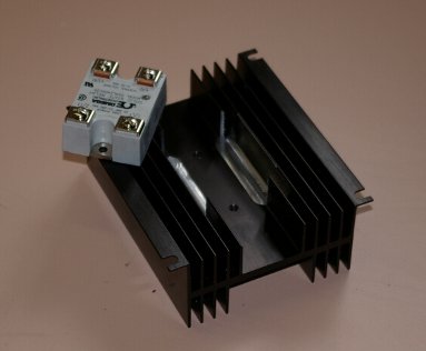
The box is 6"x6"x5". The front has been cut for the temperature controller, power light, element off switch and element on/off light. The SSR heat sink is large, some 4.75"x5.75". Early on I decided to mount it to the back of the control box. I don't think it would do much good inside a box without installing a fan. However, the SSR mounts on the heat sink with it's connectors outward. I didn't want 240V free to the world so decided to mount the SSR on the inside. The heat sink wasn't quite wide enough for this so I cut the inner most fins down to make it fit. This is shown in Figure 36. But after the SSR was installed it was found the terminals extended below the mounting surface. Bummer.
 |
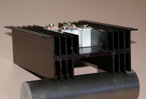 |
| Figure 36: Heat Sink | Figure 37: Heat Sink Interference |
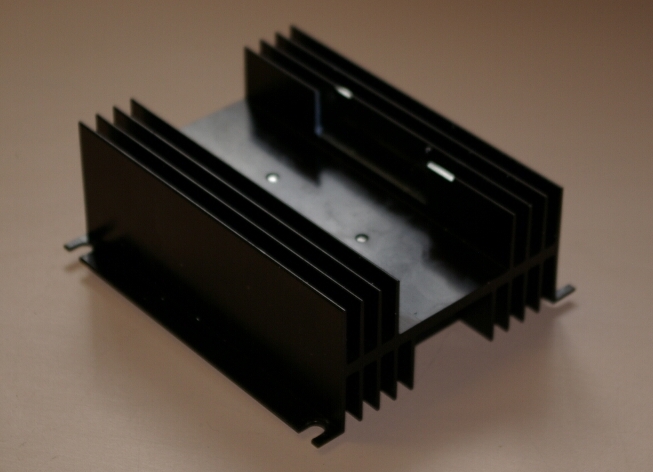
For full disclosure it should be noted I messed up the outside of the heat sink. I was too worried about the cut and put the heat sink in the milling machine wrong side up. I cut to Figure 38 before realizing the error of my ways.
 |
| Figure 38: Machining Error |
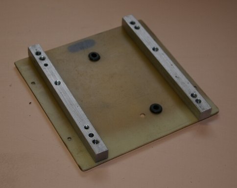
I made the back of the box of non-conduction plastic since I knew the SSR terminals would be in the area. I didn't count on a real interference though. So, offset bars were made to move the heat sink 1/2" off the back of the box. Figure 39 shows the stand-offs. Also seen are installed rubber grommets for wires going to the SSR. Figure 40 Shows the back of the box with components installed. The 24V supply I picked mounts to a D-rail so a short rail was screwed to the stand-off rails. Likewise the relay switch is seen.
 |
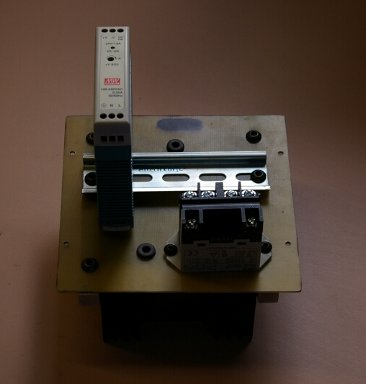 |
| Figure 39: Stand-off Bars | Figure 40: Back Inside |
The wiring was straight forward but, for me, difficult. If doing it again I'd probably make the box a little bigger to ease wiring. I did as much as I could on the back before putting it into the box which helped some. The fuse holders were difficult. The 240V wires were large for the connection pads. If doing again I'd look for some more appropriate fuse holders.
The only problem was wiring the lights backwards, I put the power light where the element power light should have been and vise versa. Once this was done it worked as designed. Figure 41 shows the control box powered up.
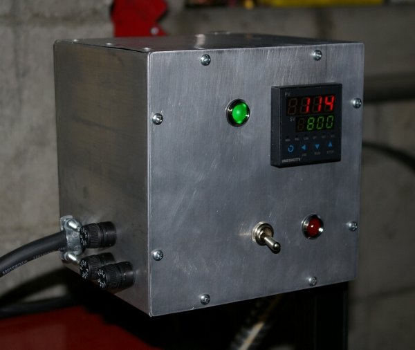 |
| Figure 41: Control Box |
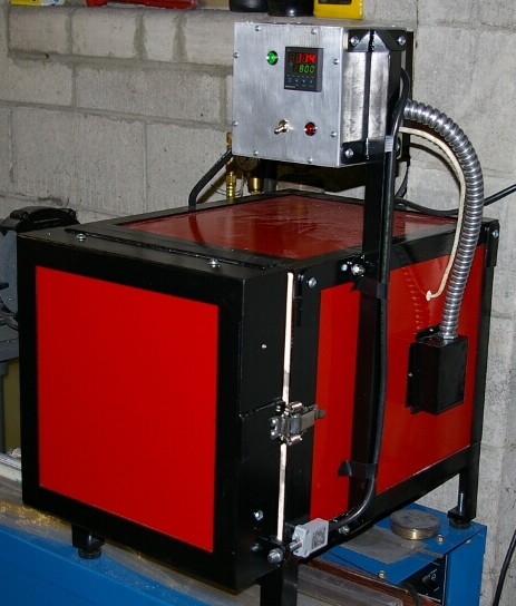
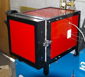
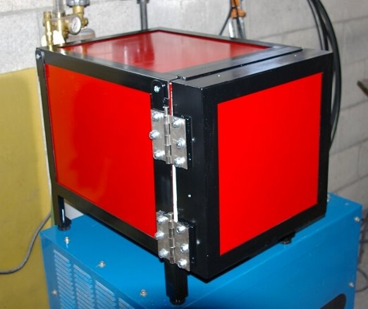
Finally, Figure 42 shows the completed oven. The control box was mounted on a pedestal off the side of the oven. The power wires pass through a flexible conduit to the control box.
|
| Figure 42: Finished Oven |
CONCLUSIONS
This was a successful project but more effort than I initially anticipated. It would be easier, and not much more expensive, to buy an oven. The project cost $975 for parts and materials. This does include all the extra materials and pieces I ended up not using. This could be reduced using scrap depending on what you have on hand. I believe a equivalent new oven would run around $1500 plus shipping. But it was a great learning experience and I now have a nice hear treating oven.
After using it I found the temperature controller has only one set point. I thought it would have several and also accommodate ramping up and down. The Omega controller does have a nice auto set PID sequence though. If starting again I'd probably get a controller with the above features. But the Omega is very easy to use and a more robust controller would likely just confuse me. Simply turning off the oven with door closed should provide adequate annealing.
The switch to enable/disable the heating elements is handy. The switch can be turned off while the controller is still under power. Thus, the temperature is displayed as the oven cools.
I'm now slowly commissioning the oven. I believe slowly bring it to temperature will help break in the heating elements. A few cycles at 800F, then 1000F and up to heat treating temperatures. I'll add here when I have more experience with it.
Note that once the elements have been heated they are brittle. Don't try to re-bend them as they will break. I understand you can heat them with a torch and bend when hot though.
I hope you've found this of interest. If you build an oven along these lines please let me know, I can forward some relevant sketches and a parts list which may be of use. It would also be gratifying to know the effort of doing a write up has been worthwhile.
Thanks.
Copyright © 2015 Hugh Currin