RECUMBENT BICYCLE - POWER ASSIST
INTRODUCTION
The idea of power assist for a bicycle is to add a motor while retaining the functionality of the bicycle. A power assist is for use on steep hills where it is most needed and turned off where pedal power alone is adequate. It differs from traditional mopeds which are small motorcycles and can't be reasonably pedaled without the motor.
To retain bicycle function the power unit must be light weight and not impede pedaling when not being used. It's possible to maintain light weight since the power requirements are quite small. An average rider can provide some 75 to 100 watts of power on a continuous basis (8 hours). An assist providing this power would be adequate and it shouldn't provide more than two or three times this power lest it overpower the rider.
My wife and I like touring, self supported bicycle tours. We usually getting away for a trip of several weeks to a month each summer. I became interested in power assist for touring. I thought it would be wonderful to turn those 10 mile, 7%, 3+ hour pain-ridden climbs into 1+ hour more pleasant climbs. I was right, it is wonderful. We had also found ourselves planning tours and side trips around the terrain rather than where we'd like to tour and what we'd like to see. Having power assists allows us to tour many more places and take all the side trips we'd been passing up.
OUR POWER ASSISTS
For touring a gasoline engine is the only reasonable alternative. The other common option is electric which is a good alternative for around town and commuting. Electric assist tends to be heavier for the power output but reasonable systems can be built. However, for touring where the hills are much longer (read mountain passes) and electricity isn't always available for charging, gasoline wins out. Gas is readily available on the road and quite inexpensive. We can also use it in our stove in a pinch.
Finding a small low power gasoline motor is a trick though. The smallest available are string trimmer motors of about 20 cc displacement. These develop about 1 HP, or 750 watts. This is more, and thus heavier, than needed but again is about the smallest available.
For my assists I decided to use a Honda 22cc four stroke string trimmer motor. It is a little heavier, and more expensive, than similar two stroke engines. However it is much cleaner, a little quieter and doesn't require a gas/oil mixture. So far I've been very happy with the choice.
My design is very similar to John Tetz's (1). They both use a timing belt speed reduction and a friction wheel to apply power to the rear wheel. Most commercial units run a friction wheel from the motor crank shaft directly to the rear wheel. This gives good top speed on the flat but lugs the motor at hill climbing speeds. Since the purpose of this assist is hill climbing a reduction is needed. This also allows a larger friction wheel to be used which should lessen power losses. The picture in Figure 1 shows the motor and reduction drive removed from the bike.

FIGURE 1 - Motor assembly off bike
The unit mounts to the bike by the two rods end links and the shaft seen to the right side of the picture. The shaft has an cam (offset) which can also be seen. This shaft is turned (rotated) which, through the cam action, presses the friction wheel against the rear wheel. The cam goes over center which holds it in contact during operation.
The friction wheel shown is elastomeric being cut from a skate board wheel. I've used several different friction wheels with this design. I tried a 60 grit sanding drum and knurled steel (heat treated 4130). The elastomeric works well unless it gets wet. It will slip going through puddles and continue to slip until the tire dries out. The sanding drum didn't slip but wore out a tire in 10 or 15 miles. The knurled steel shows some tire wear but not too excessive and I haven't noticed it slipping when wet. I'll probably go back and forth between the elastomeric and the steel until I find something better.
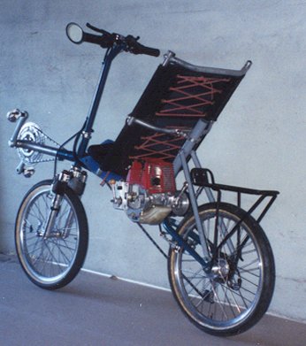
The pictures below, Figure 2 and Figure 3, show the motor attached to my bike. The bike is a homebuilt SWB recumbent. Figure 2 shows how the friction wheel contacts the bicycle wheel.
|
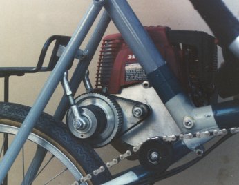
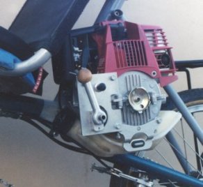
Figure 3 shows the other side of the motor and its relation to the bicycle seat. The controls are within easy reach. The lever which can be seen pivots the cam to engage and disengage the friction wheel. It does not show well but a throttle lever is also mounted to the square plate. The black button is a kill switch. There is a fuel bulb to pump gas into the carburetor and a choke, both within easy reach.
The motor is bump started while riding. When a hill is approached the fuel bulb is pumped (first start of the day), the choke engaged and the throttle set for starting. The lever is moved to engage the friction wheel and, once this is done, the choke is disengaged. The motor kicks in and you're off at 8-9 mph. I then adjust the throttle to keep my speed in the most efficient motor range.
It is more comfortable to pedal while the motor is being used. Also, pedaling helps to maintain speed, 8-9 mph, on steep hills.
The throttle is set at the motor and is not a "dead man" throttle. This hasn't been a problem as going up hill it's easy to stop, stalling the engine, by braking. I've thought of putting a switch on the brake which engages the motor kill switch. That would stop the motor when braking is applied. No doubt a good idea but I still need to put one on.
We used these on two short tours during the summer of 1999. They worked well and as designed. We found ourselves using the motors about 10 to 15% of the time. This doesn't seem like much but it is a world of help. The mileage while the motor was running came out around 80 mpg. This is serious climbing so, figuring you could easily coast back down doubling your miles, it's more like 160 mpg. For overall miles traveled and gas used our mileage is around 1500 mpg. This last depends greatly on how much the assist is used. I think the 10-15% will be typical though.
TECHNICAL DETAILS
The Honda 22cc is rated at 1.0 HP and has its best efficiency around 7000 rpm. For the reduction a 1/5 inch pitch timing belt (XL) was used with a 14 tooth pulley on the motor and a 60 tooth at the friction wheel. With a 2 1/8 inch diameter friction wheel and a 20 inch rear wheel the resulting bike speeds are shown in Table I.
|
|||||||||||||||
I used two 3/8 inch wide belts in tandem. The widest stock belt is 1/2 inch and this is borderline on capacity. The 3/8 inch are easier to find and my guess is they stretch enough to share the load between the two.
I replaced the cover that holds the string trimmer bar. This replacement can be seen in Figure 1. It was a pain to machine this cover since an internal spiral like cavity is needed for cooling. The flywheel fan circulates air inside this cover directing it over the cylinder. We are running the motor hard and for long periods so I felt it wise to keep this cooling geometry. This would be a snap on a CNC.
The friction wheel shaft and forward "cam" shaft are also mounted to this new cover.
Mounting the small pulley to the flywheel took some machining also. The flywheel holds a centrifugal clutch for string trimmer operation. Since the motor was to be bump started this clutch was removed. Some machining to the flywheel was needed and an extension shaft build. The new shaft holds the flywheel to the motor crank shaft. A "taper lock" was used between the shaft and flywheel to keep it from unscrewing. This locking is needed because as the motor is bump started it takes torque tending to unscrew the shaft.
The friction wheel was initially designed to use sanding drums. An expanding rubber mandrel held the drum to the pulley assembly. This worked well but the sanding drum was too much for the tire. However, the expanding rubber will hold any thin walled cylinder in place. I also built knurled 4130 steel cylinders which work well. I also cut a friction wheel from a skateboard wheel. This elastomeric wheel is held in place as is the rubber mandrel which seems to work.
The final unit weighs 10 pounds. It is easily removed with removal or installation being a 10 minute operation.
SUMMARY
A successful project. The only problems I've found are with the friction wheel. The elastomeric slips when wet so isn't the best bet for touring. The knurled steel works fine but reduces tire life.
I'm thinking of a different system which uses an intermediate shaft transmitting power form the motor and pedals to the bicycle drive train. This eliminates the friction wheel and, by adding the same gearing to the motor as pedaling, will keep the motor in its most efficient range. But that's another project.
A successful project and a great addition for touring. I'm sure some will say it's no longer bicycle touring. While technically this is right the best elements of bicycle touring are retained. We like touring because it forces one to slow down. With or without assist the average speed is near 10 mph, a great speed to see the country. The adventure is still there. Either way you're out in the elements, and at 10 mph, seemingly a long way from anywhere at times. The only part missing with the assist is the challenge of getting there under your own power. We've done enough touring to know we can get anywhere under our own power and that this, at times, is painful. And there is nothing like riding into a gas station and filling both vehicles for twenty cents (keep the change).
We'll take the assist, at least on many of our tours. I suggest it may be a reasonable alternative for you also.
Finally is a picture of my bike with assist loaded for touring (Figure 4). See you on the road.
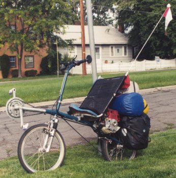
FIGURE 4 - Set for Touring
REFRENCES
| (1) |
"AHPV: Assisted Human Powered Vehicle, A Technical Description", John G. Tetz, Fourth International Human Powered Vehicle Symposium, IHPVA. |