
Ziggy - New Electrical

Ziggy's electrical system has been updated. The main driver for this was installation of a Nova Kool 12v compressor 'fridge. Systems have improved since 2010 when Ziggy was built. An upgrade will improve overall usability as well as accomodate the new 'fridge.
Ziggy originally had battery charging from 120VAC through shore power or an onboard Onan generator both feeding a converter/charger. Charging was also done, while driving, from the vehicle's alternator using a battery isolator. No solar was installed when Ziggy came to us.
Specifications
From previous RVs we've owned, and the draw of the new Nova Kool refrigerator, an average daily draw of 68Ahr was estimated. Using this, system specifications for a new system were detemined. A blow by blow description of how these came about can be seen here.
- Based around a LiPo battery of at least 200Ahr, but most likely 300Ahr
- At least 400w of solar, but as much as will reasonability fit on the roof
- Charging of 38A (@12V) or more from shore or generator power
- Charging up to 50A (@12V) from the alternator
- Inverter of at least 1500w capacity.
- Pass at least 15A, & up to 30A (@120VAC) from shore/generator to coach's 120V circuits.
This is a much more capable system than Ziggy's original. But, for current retrofit systems in 2025, one of modest capacity.
Explorist Life
I looked around the Internet for electrical designs as I didn't want to develop a new design for a one off build. Several designs were found and it came down to a Renogy or Victron based system. The Victron systems seemed to be for larger installations than Renogy. However an overlap between these exist at the size we've specified.
Of the designs available I picked what I think is the best thought out and documented. That from Explorist Life, a small company in Colorado. A full desctiption of the selected design is avaialble here. In summary it has an Epoch 300A LiPo lithium battery, Multiplus 12V|2000VA|80A charger/inverter, a Smart Solar MTTP 100|50 Charger, and an Orion 12|12-50A DC/DC for alternator chargering. There is a Smart Shunt to monitor the battery via bluetooth and a VE.bus Smart Dongle for monitoring the Multiplus also via bluetooth. The Smart Solar and Orion DC/DC have bluetooth built in. Finally, it's all tied together with a Lynx Discributor, fuses and a lot of wire. The major components are Victron.
This kit from Explorist Life was "easy" to install. The wiring diagram with YouTube videos answered 99% of my questions without contacting customer assistance. "Easy" meaning easy to understand but still required a great deal of effort to intall, as seen below. I highly recommend Explorist.Life.
Incorporation into Ziggy
Knowledge of where to break into Ziggy's wiring was still needed. After some back and forth with the Facebook "Older Model Pleasure-Way RV's (PW owners helping each other)" Forum I determined at least one way. The diagram below describes how our 2010 PleasureWay Excel-TS was interfaced to the new Victron system. (It can be downloaded as a PDF here.)
Looking at this diagram it seems so simple, but it was far from straight forward figuring it out what with wiring disappearing into walls, etc.
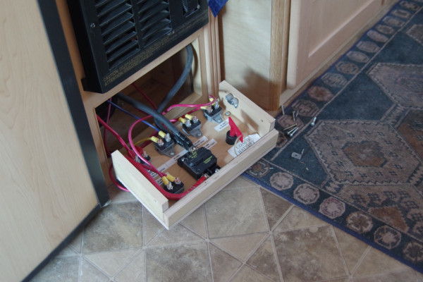
The Explorist motorhome upgrade has the original coach battery removed, and a wiring run (+ & -) from its old connections to the new Lynx Distributor. This is essentially what I did. Where I conneted was not trivial but is of little interest unless you're upgrading a similar coach. For those foolish enough to attempt this please see the blow by blow account here. For all the rest, most of the wiring tie-in was done inside the "breaker cabinet". The pic below shows the breaker cabinet and breaker board pulled forward for visibility.
Installation
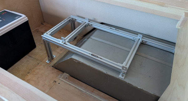
The first step in mounting electrical components was to build a shelf for the MultiPlus. I decided to us 8020 aluminum extrusion which I'd not used before. It turned out to be easy to build with. Good choice. The shelf is shown below.
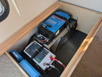
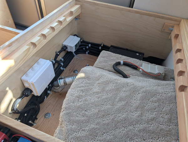
The MultiPlus fit on the shelf as shown. Also below is a pic of the Lynx, MTTP Solar and Orion components mounted. The large red switch is like to original "red key", it disconnects the battery from the system. The 300Ahr Epoch battery is here as well.
 |
 |
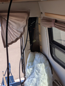
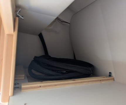
Electrical for the solar panels was brought up the back corner on the drivers side. The solar panels have yet to be installed (done July 2025) so the wiring run, with loom, was coiled in the upper cabinet near the coach's speaker. The plan is to remove the existing TV antenna and bring these leads through that hole. A box will be mounted over the hole with glands for passing them onto the roof. An aftermarket TV antenna may be mounted forward of the air vent. This will give added space for panels. (Thanks to Jim Grosby for the idea.)
 |
 |
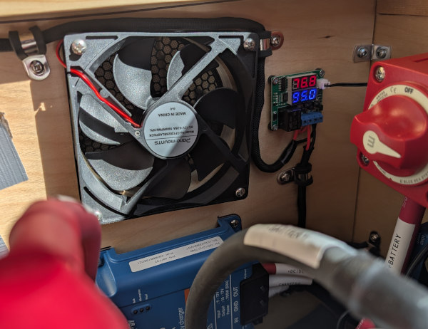
A pair of temperature controlled fans were installed in the new electrical cabinet. They come on if it gets too hot, one blows air in (at the rear) and the other sucks air out (at front). The first pic below shows the cabinet front where both are mounted. The second shows the rear fan and the electronic thermostat. It's now set for 95 degF.
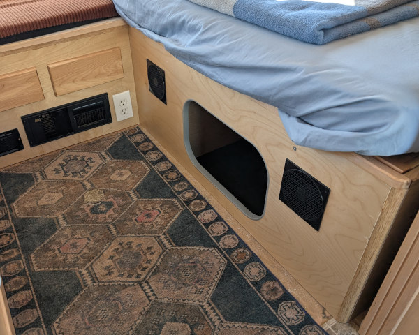
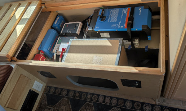
The cutout in the first picture above will open to a storage area. The pic below shows a cardboard mock up of that storage bin. It's for storage but also directs the forced air cooling towards the MultiPlus.
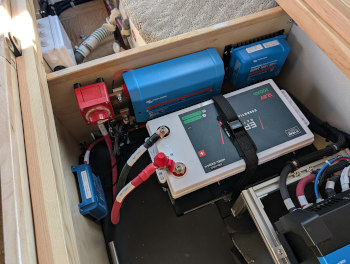
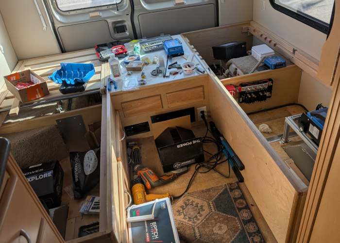
This makes it seem so simple. The truth is a lot of work was involved in this installation. I'll leave you with a picture of the in process state. Yes, it was a mess but now looks somewhat organized.
I hope this is interesting, or at least helpful. Thanks for coming along.